Gerbang logika – gate xor ic ttl 7486 7485 ic bit comparator using diagram cascade pins any logic compare shown words below Adder bit ic 7483 using binary parallel adders four explain ques10
GERBANG LOGIKA – GATE XOR IC TTL 7486 | ILMU PROGRAMMER
Design and explain 8 bit binary adder using ic 7483. Design and explain 8 bit binary adder using ic 7483. Implement 10 bit comparator using ic 7485.
Xor 7486 ttl gate logic rangkaian gerbang logika nand nor tabel datasheet kebenaran dasar xnor pinout input quad simbol tipe
Ic adder 7483 bit binary using pooja joshi parallel descriptionIc 7483 pin diagram, truth table, applications .
.


Implement 10 bit comparator using IC 7485.

Design and explain 8 bit binary adder using IC 7483.
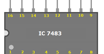
IC 7483 Pin Diagram, Truth Table, Applications - ETechnoG

GERBANG LOGIKA – GATE XOR IC TTL 7486 | ILMU PROGRAMMER